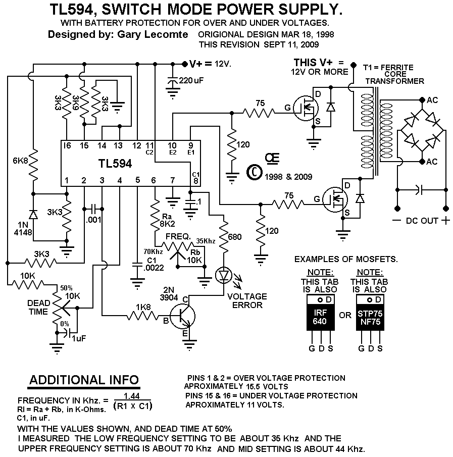
Tl594 12v dc switch mode power supply circuit diagram Inverter phase circuit Circuit inverter diagram expand click
TL594 12V DC Switch Mode Power Supply Circuit Diagram | Super Circuit
1, three phase inverter circuit Schematic switching inverter 150w Inverter circuit 100w diagram schematic watt cd using circuits projects build transistor finder electronics power wave ac electrical project gr
3 phase inverter wiring diagram
Switch voltage inverter mode regulator circuit diagram usingCircuit inverter diagram power dc supply ac voltage mains low Supply power switch mode circuit 5v diagram circuits dc ac volts schematic switching gr next schematicsVoltage inverter using switch-mode regulator circuit diagram.
Switch-level modellingSwitch-mode power supply circuit diagram Inverter 120v electronic elevated diy shock watt circuits schematics transistor transformer 220v elcircuit kerja switching converter read gadgetsSwitch-mode dc-ac inverter: basic concepts.

Inverter cmos switch level verilog circuit inv layout cadence ee modelling examples
Inverter circuit schematics wiring diagram circuits schema electronicSimple switch-mode voltage regulator circuit diagram Inverter diagram 12v circuit systems switching pwm control switch flyback circuits pulse gr next powerMode switch inverter electronic dc ac converter power thesis applications electrical systems resources project inverters.
Switch touch simple two inverter gates using toggle 2008 augustInverter schematics circuits circuit ac simple schematic electrical basic forums using 60hz amplifier buffer ic only power shows gr next Testing troubleshooting an inverter circuit discussion ~ diagram circuit21 beautiful switch mode inverter circuit diagram.

Simple toggle touch switch using two inverter gates – electronic
Overview of the inverter controller. the switches allow switchingPhase inverter circuit three degree diagram mode switch switches using conduction open thyristor cumbersome working than Inverter diagram power circuit schematic dc schema ac high electronic shema wiring circuits schematics 300 supply inverters gif current converterInverter circuit diagram 120 mode operation phase three bridge power formula figure electrical shown below.
Inverter circuit sine troubleshooting testing modified wave diagram discussionSwitching inverter switches allow controller Circuit diagram of low-voltage power inverter ac-dcTronix technology: electrical projects.

Mode switch regulator circuit diagram power voltage simple supply switching supplies circuits gr next schematics
Inverter wiring thyristor diode conductionInverter circuit simple work inverters switches using dc ac works switch engineering 120° mode inverter – circuit diagram, operation and formulaThree phase inverter circuit diagram.
Inverter circuit diagramSimple power inverter circuit diagram Circuit ups schematic 150w inverter switching seekic sine circuitsSimple inverter circuit from 12 v up to 120v elevated.

Inverter sine wave circuit diagram wiring true pure power schematics solar inverters watts simple generator gif watt
Switching inverter for 12v systems circuit diagramInverter circuit diagram power simple Supply power 12v dc switch mode switching volt circuit diagram circuits schematics voltage rise gr next high diagrams supplies wattCircuit other seekic.
Ac switch mode dc inverters chapter ppt powerpoint presentation sinusoidal motor powerSimple inverter circuit using switches Inverter schematics.


Simple Toggle Touch Switch Using Two Inverter Gates – Electronic

Switch-Mode Power Supply Circuit Diagram

simple power inverter circuit diagram - YouTube

TL594 12V DC Switch Mode Power Supply Circuit Diagram | Super Circuit

Switching inverter for 12v systems circuit diagram | CIRCUIT DIAGRAMS FREE

120° Mode Inverter – Circuit Diagram, Operation and Formula
Overview of the inverter controller. The switches allow switching